 through
  .
. 
This site uses cookies to deliver our services and to show you relevant ads and job listings. By using our site, you acknowledge that you have read and understand our Cookie Policy, Privacy Policy, and our Terms of Service. Your use of the Related Sites, including DSPRelated.com, FPGARelated.com, EmbeddedRelated.com and Electronics-Related.com, is subject to these policies and terms.
The remaining two direct forms are obtained by formally transposing direct-forms I and II [ 60, p. 155]. Filter transposition may also be called flow graph reversal , and transposing a Single-Input, Single-Output (SISO) filter does not alter its transfer function. This fact can be derived as a consequence of Mason's gain formula for signal flow graphs [ 49, 50] or Tellegen's theorem (which implies that an LTI signal flow graph is interreciprocal with its transpose) [ 60, pp. 176-177]. Transposition of filters in state-space form is discussed in §G.5.
The transpose of a SISO digital filter is quite straightforward to find: Reverse the direction of all signal paths, and make obviously necessary accommodations. ``Obviously necessary accommodations'' include changing signal branch-points to summers, and summers to branch-points. Also, after this operation, the input signal, normally drawn on the left of the signal flow graph, will be on the right, and the output on the left. To renormalize the layout, the whole diagram is usually left-right flipped.
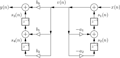
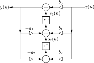
Figure 9.3 shows the Transposed-Direct-Form-I (TDF-I) structure for the general second-order IIR digital filter, and Fig.9.4 shows the Transposed-Direct-Form-II (TDF-II) structure. To facilitate comparison of the transposed with the original, the inputs and output signals remain ``switched'', so that signals generally flow right-to-left instead of the usual left-to-right. ( Exercise: Derive forms TDF-I/II by transposing the DF-I/II structures shown in Figures 9.1 and 9.2.)
|
 |
This site uses cookies to deliver our services and to show you relevant ads and job listings. By using our site, you acknowledge that you have read and understand our Cookie Policy, Privacy Policy, and our Terms of Service. Your use of the Related Sites, including DSPRelated.com, FPGARelated.com, EmbeddedRelated.com and Electronics-Related.com, is subject to these policies and terms.

This book is a gentle introduction to digital filters, including mathematical theory, illustrative examples, some audio applications, and useful software starting points.